
2. MEASURING PRINCIPLE of Thrust Load Monitoring
Journal or sleeve bearings and spherical roller bearings, a type of anti-friction bearing.
The typical kiln uses journal bearings. The housings for these types of bearings also incorporate separate thrust bearings. The roller assembly is such that the distance between the thrust bearing uphill to downhill leaves room for shaft to float axially (uphill to downhill) nominally about 6 – 12 mm. This is purposely done to facilitate identification of the rollers’ neutral skew position by simple adjustment and observation without the need to make any alignment measurements. When the skew of the rollers drives the tire and shell uphill, the roller will drive itself and end up sealing itself downhill. This is the normal and expected position for the roller to be in whenever skew is applied and the corresponding thrust bearing absorbs the load. When the roller is than adjusted to reverse the skew, as soon as it crosses the neutral position, the forces also reverse and the roller starts moving uphill. No matter what size of roller, be it 500 mm or 3000 mm dia., adjustment of less than 0.1 mm across the neutral point will cause the roller to shift positions. This technique is therefore employed to locate each roller’s zero skew position. The measurement required is to use dial indicators to track the bearing adjustments.
Kilns with more substantially designed thrust roller mechanism(s) are designed to run with neutrally skewed support rollers, reliving them of the stresses and subsequent wear when forced to run in a skewed position. These are often referred to as full thrust units.
A few kilns and most other trunnion roller supported equipment, such as non-refractory lined rotary coolers, dryers and granulators, make heavy use of anti-friction bearings, namely spherical roller bearings. Their application comes with two notable handicaps. Firstly, there is no meaningful axial travel by which to easily observe shaft position in response to roller adjustment. This makes finding the neutral skew position difficult by traditional methods of alignment measurement. Secondly, there is no separate thrust bearing. Spherical roller bearings are capable of accommodating limited thrust loads. Unfortunately, it does not take much skew on a roller to introduce enough force to overload it and cause it to fail. Excessive thrust loads are exacerbated by the low speed of rotation of rollers, which is usually no more than 50 rpm. This may miserably slow to get the lubricant to function effectively. As consequence, failures of spherical roller bearings are much more common than failures of journal bearings.
The Thrust Monitor System (TMS) is equipped with high precision inductive distance sensors with an analogue output and precise temperature output.
The high frequency signals (max 100Hz) from the distance and temperature sensors are measured and recorded by data logger in the TMS Control Box.
The data logger is calculating the different parameters like distance, average distance, temperature and average temperature of distance sensor.
Calculated values are directly transferred into LED panel, which inform the operator in real time about thrust force generations for each of the roller.
Furthermore, the Control Box is equipped with a card reader, where periodically (e.g. every 2 weeks) all data from the data logger are stored in the SD card.
Optionally, the access to data can be provided from CCR level or on-line (via web browser).
Note: on-line monitoring via web browser requires access to the server that need to be provided by the Customer.
2.1. THRUST FORCE MEASUREMENT
At the fundamental level of proper alignment, the only two things are required:
- Exact bearing elevations,
- Exact bearing location with respect to a centerline, corrected for precise, prevailing roller, and tire diameters.
The limit in measurement accuracy is not the quality of the instruments brought to the task, which can be capable of great accuracy. Rather, measurement accuracy is also very dependent on the quality of the target object. This can be a shaft, a bearing, a bearing housing, a roller face and centerline. Given the nature of the equipment to be dealt with and the way it is installed, there are no pristine surface to measure to. Moreover, the centerline almost always requires the use of parallel offsets. Every additional step adds more opportunity for imprecision.
Other factors, which are totally ignored when carrying out such alignment measurements, are tire flex, tire wobble, and base flex. All of which means that, if one were actually capable of measuring alignment to an accuracy of 0.1 mm, it would have to be done at least three different times with the shell rotated 120o between each set of measurements. The results would then be averaged. When was the last time anyone saw that done?
Some industries run “super-fast” units, i.e. those at 6 to 12+ rpm. For them, alignment never seems to be good enough, so they resort to applying oil to the tires. Oil is the “forgiveness option”: if the alignment is reasonable, bearing failures are avoided. Oil acts to reduce, if not completely eliminate, thrust due skew. Oiled units should, therefore, never have their rollers skewed. If, then, the thrust roller is not capable of carrying the full thrust load of the unit and requires the roller skew to protect it, the oil presents a contradictory situation.
With oil applied to the running surfaces of tires, this forgiveness factor lulls one into a false sense of security, believing that precise alignment is not essential. However, oil is a fair-weather friend: its presence is not guaranteed to be uniform over the long haul. A puff of dust and it becomes a grinding compound; if the surface runs dry then there is no forgiveness for bad alignment. That is why, even with liberal amounts of oil applied to the tire faces, bearing failures abound. This scenario has become routine in many plants. A bearing fails and when a new roller assembly is put in place, it is done with minimal concern for alignment or adjusting the alignment for the inevitable difference in roller diameters. This is not shoddy workmanship: it is often the only available response to production pressures and the very limited resources available with which an alignment can be quickly verified.
For fast units, a roller with properly sized bearings, well aligned and running without surface oil, should run trouble-free an average of 10 years.
In extending service life or improving the mechanical performance it is necessary to minimize the friction. And minimizing the friction the wear will be reduced. The friction is kind of resistance to a force, but nonetheless this is the force that resists rotation. Each misalignment or skew makes rotation more difficult because it adds friction. The Thrust Force generated by skew is one form of friction.
Installation of Thrust Monitor System allow to precisely and directly monitor this friction. The friction is visualized to the operator. When the operator can see when friction is minimized, then can make certain moves and directly see a move which increase a friction or a move which decrease a friction. It can be easily identifying a condition where a friction is minimized and find the best state of alignment possible – by watching changes in Thrust Force (or friction) in response to bearing adjustments.
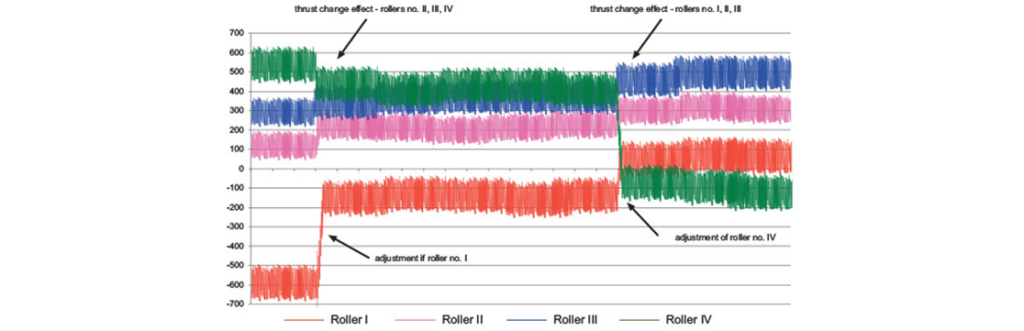
The basic concept is to make a move by adjusting a bearing, either in or out, which would either add or subtract skew, and in real time the changes in a Thrust Force overtime are visible. If the move is reversed, then there will be opposite change in real time on the roller.
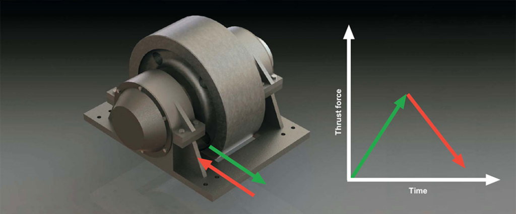
Thrust Monitor System (TMS) measure/control force not position, because bearing position is relative, but axial force is absolute.
While the best traditional methods may yield passable results, there is no immediate feedback confirming whether the set of bearing location is optimum. By measuring force in real-time, the optimum bearing position announces itself.
Bearing fail when subjected to high loads, especially high axial loads. Measuring of those loads rather than assuming that position of minimized axial load has been set without such confirming feedback is much more reliable method.
Axial load can be changed by many reasons during equipment operation i.e.:
· different operation temperature (production),
· different ambient temperature (seasonal changes),
· support displacement and settlement,
· small wear of tires and rollers running surface,
· different production load (feed),
· tires axial run-out,
- tires and base frame flexibility.
Aligning the rollers based on real-time Thrust Monitor System yields the neutral skew position of a roller within 0.03 mm with 100% reliability. Acceptable alignment usually only requires 0.1 mm resolution provided its direction is verified as positive. This method is therefore more precise than the best “measured positions” normal produce. How can the claim of 100% reliability be substantiated? Simply because the measured forces are observed in real-time and the response to a 0.03 mm move is immediately seen. Alignment by standard position measurement has no immediate real-time feedback in response to a roller adjustment. In addition, even small changes at one of the support rollers has the influence over axial thrust of the all set.
2.2. SUPPORTING ROLLER SLOPE (Inclination)
For rollers fitted with spherical roller bearing, the most common problem contributing to a misalignment is inaccurate roller slopes. If the roller slope is not correct, there is no subsequent procedure that can be done to make up for it. Kilns with sleeve bearings, particularly those with fixed sleeve arrangements, have a very tight slope installations tolerance usually in the order of +/-0.02% from designed slope. With fixed sleeves there is no self-alignment and shimming is not permitted, so every effort is made to set the bases precisely. Because spherical roller bearings are not needed. Nothing could be further from the truth. Slopes should still be set to within +/-0.02% of designed slope, otherwise a roller set for optimum skew will have limited face contact.
2.3. TIRE AND ROLLER SURFACE RE-CONDITIONING
Recommended for reliable alignment and bearing failure prevention
To do a proper job of alignment, resurfacing by grinding worn tire and roller faces is recommended. Alignment without resurfacing may result in less than 70% face contact so wear will continue. Grinding without alignment does not correct the underlying problem that led to the need for resurfacing. The two are inextricably linked: one cannot do one without the other and expect the best value for money.
To align via Thrust Monitor System, flat cylindrical roller and tire are recommended.
2.4. THRUST LOAD MONITORING SYSTEM REQUIREMENTS
– Tires and rollers need to be clean (no oil or grease).
– Requires reverse rotation for short period of time during the alignment process.
– Tires and rollers running surfaces need to be cylindrical.
2.5. PRECEDING PROCEDURE – KILN ALIGNMENT (Dryer, Cooler Alignment Control).
Before alignment process with the use of Thrust Monitor System, the standard alignment procedure to be performed to set or control each roller position in relation to design. This drum and rollers positioning allow to achieve correct location within 1,0 mm accuracy. The parameters to be checked:
- Drum axis in horizontal plane (as a reference line for roller skew positioning),
- Drum axis in vertical plane – slope (as reference line for inclination positioning),
- Working angles between central point of the shell (drum body) and middle point of the rollers,
- Rollers position relative to each other,
- Rollers skew in relation to drum horizontal axis,
- Rollers inclination in relation to drum slope,
- Tires running surface mechanical wear measurement – by precision circumference meter,
- Rollers running surface mechanical wear measurement – by precision circumference meter,
- Tires axial run-out measurement,
- Circularity of tires and rollers measurements.
All the parameters are measured, calculated and the necessary analysis are performed. Base on this analysis the general adjustment can be performed (if needed).
3. ALIGNMENT THAT ELIMINATES ALL THE GUESSWORK.
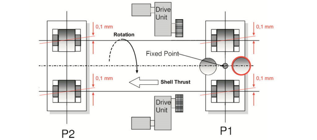
The basic principal of this procedure is that axial thrust force, which results from roller skew, reverses direction with change in direction of rotation. A roller, however minutely skewed, creates a measurable thrust force, either pushing the roller downhill or pushing it uphill. Reverse the direction of the shell rotation and the roller’s axial force also reverses. This axial force can be plotted graphically, in real-time, and roller adjustments as small as 0.03 mm can be easily identified. When there is no appreciable change in thrust level going from a clockwise (CW) rotation to a counter clockwise (CCW) rotation, then the roller is certified to be in the truly neutral position.
In practice, with all the sensors mounted, the shell is rotated in its normal direction (e.g. CW). Depending on the speed of rotation, after a few minutes all the rollers will settle out at some level of thrust. At that point, the drum is stopped and then turned in the reverse direction. Immediately, all thrusts reverse and settle out at a new level. Each roller is then adjusted in turn until its change in thrust from CW to CCW rotation is minimized. If the surfaces have not been reconditioned, the tapers must be identified by circumferential tape measurement and extracted from the shim calculation. One of the prime reasons for resurfacing is to avoid this unnecessary complication as well as those caused by convex/concave surfaces.
Once this is done for each of the four rollers, they will all be sitting in their neutral position. Two things now become apparent.
Firstly, the effects of the tire wobble will be seen. This is roughly a sinusoidal thrust pattern imposed on each roller. For half of rotation, the tire pushes the roller in one direction and for the other half the tire pushes the roller the other way. All tires wobble: only the degree of wobble varies.
Secondly, upon careful examination of the quality of contact between tire face and roller face, any persistent gap throughout one rotation is a clear indication of roller slope error. This can be the only possible explanation if the tires and rollers have been reconditioned. Such gaps, excluding cyclical gaps from tire wobbling can now be carefully measured (after the unit is shut down and locked out) using feeler gages from which a simple calculation yields the required shim thickness needed to achieve 70% face contact or better.
One the most difficult problems one faces to have a roller’s skew set to zero thrust and then see it run with poor face contact. The overwhelming tendency is to readjust the skew for better face contact. This is so easy to do but is always wrong. Minimal if not zero skew is primary. Running with poor face contact is far more tolerable than add skew. Correcting the face contact requires eliminating any face tapers and then shimming one of the roller’s bearings to attain full face contact. This method of correcting rollers slope has shown itself to be far superior to any attempts at absolute measurement with respect to a design slope using auto levels, slope blocks/machinists level, or inclinometers.
With full thrust units, alignment is now complete. However, most units do not have thrust rollers robust enough to operate continuously in this state and must be “floated”. Floating simply means that a small amount of skew is introduced on each support roller to counter the pull of gravity. With the ability to graphically view the thrust levels in real-time, the roller adjustments can be made so that each roller can be exactly in skew to share the load equally. When one pair of rollers supports more weight than the other pair, then equal load does not correspond to equal skew. This aspect of final adjustment is also not available by standard position measurement alignment.
A drum is said to be floating when the thrust tire leaves the lower thrust roller for a short period during each revolution. This intermittent contact is caused by the tire wobble.
With the Thrust Monitor System permanently installed, “float” adjustments may be modified for load and speed once the unit has been put into full operation.
Going forward, the system becomes an early warning system, operating over the plant’s network to alert of any change in bearing’s thrust load. To assist with this, a local LED panel indicates each roller’s thrust level by a string of lights: green for neutral, yellow for normal float load, red for alarm. In this way, the operator in the control room is kept abreast of thrust level, and it is also clearly displayed to all who walk by the operating unit. Assessment of the condition of roller skew is therefore reduced to a single glance at the control panel.
Operating the unit after aligning it in this manner and following it by continuous monitoring will result in realizing maximum service life of all the rollers and bearings.
for more information see our web: www.hkahavec.com
and contact our experts: https://hkahavec.com/contact/